
Abstract: This paper introduces the feature of screw air compressor, INVT GD300-01 series special inverter for compressor, and the successful application in Israel.
Key words: screw air compressor, GD300-01, PID, constant pressure
1.Foreword
A rotary-screw compressor is a type of gas compressor which is based on a rotary-type positive-displacement mechanism. It is commonly used to replace piston compressors in either large industrial applications or high-power air tools where large volume of high-pressure air is needed. The traditional pressure control method is loading or unloading, which causes pressure fluctuation, energy waste. The use of frequency inverter for constant pressure control is the current mainstream.
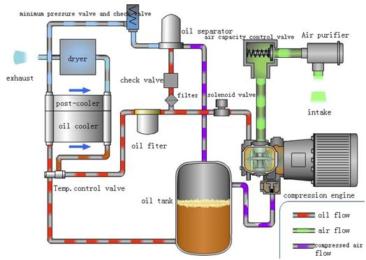
Fig.1 Working process of screw air compressor
2.System requirements
The Israeli air compressor factory has more than three decades of experience in the design and production of air compressors.Their technical requirements are as follows:
(1) Built-in PID function:
1) Preset a pressure value on HMI so that the inverter automatically can adjust the speed according to the feedback pressure to make the pressure constant.
2) No controller needed.
(2) Valve control:
If measured pressure<setting pressure(8.5bar), the inlet valve opens;
If measured pressure≥9 bar, the inlet valve closes;
(3) Sleep mode:
If the inlet valve is closed, set pressure(8.5bar)≤measured pressure<9 bar.After 120 seconds delay time, inverter sleep.
(4) Cooling fan control:
Be able to measure the temperature of compressor, if temperature ≥80℃, start the cooling fan, if temperature <75℃, stop the cooling fan.
(5) Over pressure protection:
≥10 bar, display alarm on HMI, continue to work
≥10.5 bar, display alarm on HMI, shut down
(6) Over heat protection:
≥98℃, display alarm on HMI, then continue to work.
≥105℃, display alarm on HMI, then shut down.
(7) Maintenance time alarm:
Be able to set maintenance time, alarm when it is reached
(8) Other protection:
Pressure sensor disconnected alarm, temperature sonsor disconnected alarm, Emergency stop etc.
(9) GD300-01 series inverter + HMI meets all the requirements of customer.
3.System scheme
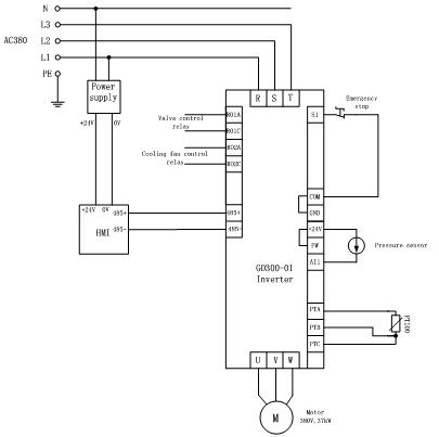
Fig.2 System diagram
Supplied list:
| Type | Model | Remarks |
| Inverter | GD300-01-037G-4 | Special inverter for compressor, integrated compressor control logic. Standard power range is from 4kW to 315kW |
| HMI | VT series | Controlling and monitoring interface, different sizes are available |
| Pressure sensor | 4~20mA, 24V | Hessman type, for air pressure measurement |
| Temperature sensor | PT100 | For compressor temperature measurement |
| 24V power supply | 24V, 1A | Power supply for HMI |
4.Parameters setting
| P00.00 | 1.Vector control 2.V/f control |
1 | |
| P00.01 | Modbus control | 2 | |
| P00.06 | PID reference | 7 | |
| P00.11 | ACC time | 10 | |
| P00.12 | DEC time | 10 | |
| P02.00 | Motor type | 0 | 0:Asynchronous motor 1:Synchronous motor |
| P02.01 | Rated power of motor | kW | According to motor nameplate |
| P02.02 | Rated frequency of motor | Hz | According to motor nameplate |
| P02.03 | Rated speed of motor | rpm | According to motor nameplate |
| P02.04 | Rated voltage of motor | V | According to motor nameplate |
| P02.05 | Rated current of motor | A | According to motor nameplate |
| P05.01 | S1 Emergency stop | 9 | |
| P05.10 | S1 Normally closed | 1 | 0: normally open 1: normally closed |
| P05.32 | Lower limit of AI1 (pressure sensor) | 2V | 4~20mA correspond to 2~10V |
| P06.03 | Valve control relay | 27 | RO1 |
| P06.04 | Fan control relay | 28 | RO1 |
| P09.00 | PID reference selection | 10 | Pressure reference from HMI |
| P09.02 | PID feedback selection | 8 | Pressure feedback to AI1 |
| P09.04 | Kp of PID | 20 | |
| P09.05 | Ti of PID | 2 | |
| P09.06 | Td of PID | 2 | |
| P09.09 | PID output upper limit | 100% | 100% correspond to 50Hz |
| P09.10 | PID output lower limit | 60% | 60% correspond to 30Hz |
| P18.00 | Compressor mode enabled | 1 | 0: disabled 1: enabled |
| P18.01 | Sleep mode enabled | 1 | 0: disabled 1: enabled |
| P18.02 | Load/unload mode | 0 | 0: Automatic open/close the valve 1:Manual control the valve |
| P18.03 | Temperature signal | 1 | 0: from analog input AI2 1: directly from PT100 |
| P18.05 | Valve close pressure | 0.9 Mpa | |
| P18.06 | Valve open pressure | 0.85 Mpa | |
| P18.07 | Setting pressure | 0.85 Mpa | |
| P18.08 | Fan start temperature | 80 ℃ | |
| P18.09 | Fan stop temperature | 75℃ | |
| P18.11 | Lower limit frequency of valve open | 30Hz | |
| P18.12 | Running frequency of valve closed | 30Hz | |
| P18.13 | Sleep delay time | 120 sec | |
| P18.14 | Stop delay time | 15 sec | |
| P18.15 | Valve open delay time | 1 sec | |
| P18.16 | Restart delay time | 15 sec | |
| P18.17 | Alarm pressure | 1Mpa | Display alarm on HMI, continue to work |
| P18.18 | Shut down pressure | 1.05Mpa | Display alarm on HMI, shut down |